Friday, August 26, 2011

Ion Exchange Resin Testing & Analysis Services

Test your ion exchange resin to monitor and maintain your water treatment systems such as softeners, dealkalizers, condensate polishers, deionizers or demineralizer systems. You should have the resin analyzed on a yearly basis to check the quality and performance of the resin. Samples can be taken from the resin bed and sent to Res-Kem to have the resin analyzed.

Res-Kem partners with Purolite Company to perform the resin analysis. The three most common tests we see performed are:


  • Total Capacity
  • Moisture Content
  • Resin Bead Integrity

    Other tests that can be performed are:
  • Iron Fouling
  • Organic Fouling
  • Ash Content of the resin

    but we will explain the latter in the detail.

    First, a sample of the resin bed is required, so it can be analyzed. Taking a good sample is very important to get proper results on the analysis performed. We recommend a sample be taken from various levels of the resin bed and within different areas of the bed. We suggest using a piece of PVC pipe, ½” or 1” in diameter and long enough to get down into the resin. Stick the pvc pipe all the way down the resin bed to pull up a sample. Think of a soda straw, when you place your finger on the top of the straw in soda, and pull up the straw with soda inside it. Now that we have our sample, lets look at the resin tests.

    Total Capacity Test:
    The total capacity of an ion exchange resin is defined as the total number of sites available for exchange per some unit weight or unit volume of resin. The capacity is expressed in terms of millequivalents per milliliter MEQ/ML for wet resin. For example, new strong acid cation resin, typically, has a total capacity spec of 2.2 MEQ/ML. A resin sample will get compared to new virgin resin for the test. Based on our experiences with Purolite, if a total capacity analysis shows more than a 20% difference compared to new resin, one should consider a resin change out. In the case of the SAC resin, a change out would be suggested if the total capacity test of the sampled resin shows a spec of 1.75 MEQ/ML or less compared to a new spec of 2.2 MEQ/ML.

    Moisture Capacity Test:
    The moisture content of a resin is a measure of its water holding capacity or swelling. New Cation Softening resin will usually have a water retention spec of 45-48%. Type I Strong Base Anion resin the Chloride form has a spec of about 48-54% moisture. If a resin analysis is to be done, it is important to test the moisture content of the resin sample to see if it’s within spec. An increase of the moisture content in resin is a clear indication of oxidation occurring on the resin. The resin tends to become soft, which leads to pressure drop and channeling, and will eventually affect the capacity of the resin. Going back to the softening resin spec, if we see an increase of more than 6% on the higher spec of 48%, we will throw up a red flag.

    Bead Integrity Test:
    Our bead integrity test is a percentage measurement of whole, cracked, & broken resin beads. Whole, cracked, and broken beadsFor example, test results will show the following: 94-4-2. 94% would be whole, 4% would be cracked, and 2% would be broken. Broken beads usually occur over time and are a normal part of wear and tear on the resin. Usually, a thorough backwashing of the resin bed will remove broken beads and fines. If broken beads accumulate over time because they are not flushed from backwashing, and the percentage test results of broken beads are shown to be in double digits, their presence will result in channeling of the resin bed and pressure drop.

    For further information:
    On our resin analysis, please visit our website.

    Please contact me, Mike Polito, when you have completed the Resin Analysis Request Form.

    Here are the resin analyses charges.
  • Friday, August 19, 2011

    Fleck Valved Multiple Tanks -"What's Your System Number?"

    The Problem:
    Many water treatment end users can wind up inheriting an orphaned treatment system. Usually it was part of a package supplied by a car wash or a boiler treatment company. The situation becomes more confusing when there are multiple tanks with elaborate wiring and piping that resembles knotted intestines. Also, the owners manual provides little guidance or is lost. The following will provide a link to enlightenment and will help ID your multiple tank system and un-knot your intestines.

    History:
    In the days before reliable electronics, softener manufacturers demanded Fleck design a control valve system that could operate multiple tanked softeners and filters. Fleck labeled them "systems" and assigned them an elaborate numbering ID System 4,5,6,7 & 9. What no 8?

    Here is what they mean:
    - System 4 was the most simple, one tank time clock or water meter regeneration.
    - System 5 multiple tanks, meter on each valve, operates parallel, regenerates sequentially.
    - System 6 multiple tanks, only one meter at the end of the system, "split flow". - Systems 6 is popular for filters with heavy media that need to "SPLIT" the flow between 1,2 or 3 tanks to provide enough backwash water.
    - System 7, the most popular, called the alternator. System 7 keeps one tank in service and one tank in stand-by. When the on-line tank is spent, the standby tank is put on-line. They alternate.
    - System 8? Poor system 8, never happened.
    - System 9 is like system 7, the altenator, but with more tanks.


    Confused? Here is the link to Pentair Fleck Valve enlightenment.

    For a minimal cost you can convert the "Wire Monsters" to state of the art electronics by adding NXT power heads. Pentair NXT Controller provided by Res-Kem

    The NXT have all these systems plugged in. Just select the one you need. Also here is information on the Aquamatic 962 NXT controller

    Thursday, August 18, 2011

    Trailer & Skid Mounted Mobile Water Treatment Systems Available

    Res-Kem, in association with our parent company, Nalco, now offers many different mobile water treatment system options. Whether you need supplemental water for short-term shortages, temporary water while waiting for a new system to be delivered, or improved water quality due to a change in feedwater, we can provide the mobile options to meet your needs.
    Res-Kem RO systems in 53 foot trailer ready for shipment.
    Our mobile fleet includes equipment installed in containers, trailers, or skid mounted to meet your water quality requirements. Equipment technologies we offer include:
    • RO units

    • Deionization (DI) tanks

    • Multi-media Filtration

    • Activated Carbon Filtration

    • Ion Exchange Softening

    • Iron Removal

    Res-Kem RO skid system ready to be installed.
    We can customize the water treatment unit operations to meet your individual application requirements. These are trailer options we offer:
    • Mobile RO Trailers - 500 gpm Single pass RO or 220 gpm Double pass RO

    • Mobile DI Trailers - Maximum flow rate of 350 gpm and a 4.3 million grain capacity

    • Mobile Pretreatment Trailers - 600 gpm for filtered water or 800 gpm softened water

    CAD drawings of a combination RO-Prefiltration trailer and a filtration trailer
    Typical mobile water treatment applications include:
    • Scheduled shutdown and maintenance

    • Additional capacity needed due to plant expansion

    • Change in process requiring better water quality

    • Water for pilot testing

    • Interim water service while awaiting the installation of permanent equipment

    • Seasonal water variances in quantity or quality

    • Inlet water quality no longer meets specifications


    Wednesday, August 17, 2011

    Common Cation Ion Exchange Resin Foulants

    We are often asked to help with an ion exchange system that no longer has the same run length as when it was new. Typically, this is the result of either reversible or non-reversible fouling of the cation and/or anion ion exchange resin. These are some of the common foulants:

    Iron:
    Clear Water Iron (ferrous iron) can be removed through a softener. As long as iron stays in the ferrous form, regenerating a softener with a salt brine solution will remove the iron off the resin. When ferrous iron becomes oxidized into ferric iron (small solid iron particles), this type of iron will coat the surface of the resin, as well as, penetrate the internal matrix of the resin bead. Two common oxidizing agents, which can be present in water during the service cycle, are chlorine and oxygen that can cause the ferrous iron to form into ferric iron.

    Aluminum:
    Aluminum can be found in water due to the carryover of using Alum or Aluminum Sulfate in water treatment to remove suspended solids and turbidity. Aluminum will coat the resin and penetrate inside the resin bead causing poor exchange sites and reduce capacity.

    Barium:
    Barium is a metal that can be removed by softening resin. If Barium precipitates into Barium Sulfate where the Sulfate is greater than two ppm and the Barium is less than one ppm, this will foul the cation resin and reduce it’s capacity.

    Oil/Grease:
    Oil fouling typically occurs from leaks in oil-lubricated pumps. This will coat the resin causing short service cycles and poor product water quality. Dirt particles and broken resin beds will stick to oil and grease which also causes channeling of the resin bed.

    Hardness Salts (Calcium & Magnesium):
    This type of fouling occurs from improper resin regeneration. In a demineralizer or deionizer using sulfuric acid regeneration, calcium sulfate can form when the sulfuric acid regenerant is at too high a concentration or at too low a flow rate. This will lead to a gradual build up of hardness ions on the surface of the resin beads and within their structure. Once this occurs, regenerating the resin becomes more difficult which causes shorter service runs and reduces the resin life.

    How Do I Figure out what the problem is?
    The best way is to take a representative resin sample and have it tested. Please note, this may not be cost effective on small softeners because the labor cost of taking the sample and the resin analyses cost may be more than simply replacing with new resin. If you decide to have your resin tested, please fill out our Resin Analysis Submittal Form so we can start to figure out what the problem is. After that Mike Polito will have an RMA # issued so the resin sample can be received at Res-Kem.

    Friday, August 12, 2011

    300 gpm Industrial Water Softener Shipped to a Virginia University

    Res-Kem's 300 gpm industrial water softener being prepared for shipment to a major Virginia university.
    I nearly missed taking photos of a very nice looking quadruple tank industrial water softener that recently left our plant. As you can see, the system is being prepared for shipment and only two of the four tanks were available in this photo.

    System Details:
    The system has four 30" water softener vessels commonly called "mineral tanks". Each tank is rated for 75 gpm. The tanks are ASME code carbon steel tanks with a design pressure rating 100 psig.

    Given the customizable standard designs we have for all of our water softening equipment and all of our industrial water treatment equipment, Res-Kem was able to accommodate the customer's request for carbon steel tanks with 304L stainless steel face piping. Bray series 21 butterfly valves with stainless steel body, 316 SS disc & stem, Teflon lined EPDM seat. Each of the automated valves were equipped with Bray series 70 electric actuators, two SPDT limit switches and a manual override handle.

    Bray series 21 butterfly valves with stainless steel body, 316 SS disc and stem, teflon lined EPDM seat. The valves were equipped with Bray series 70 electric actuators with 2 SPDT limit switches and a manual override feature.
    The internals of the tanks use stainless steel hubs and stainless steel wedgewire laterals for long life.
    The internals of the Res-Ken industrial water softener tanks use stainless steel hubs and wedgewire laterals for long life.
    The water softener system is being readied for shipment to our customer.

    Res-Kem 300 gpm Quadruple Industrial Water softeners being prepared for shipment prior to tarping.
    While our standard design uses the AquaMatic 962 controller, we offer as an option an Allen Bradley PLC. This system uses the Allen Bradley MicroLogix PLC with Panelview 600 operator interface terminal mounted in a NEMA 4X fiberglass enclosure was used to control the system.

    Please contact us for further information on how to size a water softener for you requirements.


    Friday, August 05, 2011

    Peroxide. Mother Natures Hamburger Helper

    As water treatment professionals we sometimes stumble upon jobs that are very troublesome. Those jobs almost always involve iron removal from ground water with oxidation. Oxidation is a tricky science. Your pH must be near neutral, but never above 8.2. High pH will cause the iron to create sludge. If you are using conventional air injection via venturi, pump or vacuum, you run the possibility of creating iron precipitate sludge. Also, barometric pressure, water temperature, and elevation greatly effect water's ability to hold oxygen.

    Peroxide to the Rescue:
    Now back to that pesky job leaking 0.5 ppm iron past your air fed iron filter where you've tried "everything". Peroxide to the rescue! What you are lacking is a good wallop of pure O2. 7% peroxide contains 70,000 ppm of oxygen. That will jump start your oxidation! Try it! You will be amazed. Your filter starts working and will nail that last bit of sneaky iron or sulfur . Peroxide works wonders for sulfur too.

    For the wholesale market, we have built a complete package to treat water with iron and/or sulfur problems. It is called the Ultimate Oxidizer.

    Extra Details you Need to Know:
    Now I can continue on with a real snoozer of a post with all the minute details of "peroxification", but there are important peroxide application rules of the road.

    • Use 7% peroxide NSF rated with proper labeling. Any concentration greater than 7% will subject you to the scrutiny of regulators and lawyers.

    • Inject peroxide into the plumbing with a peristaltic pump, like Stenner or Chemtech XP.

    • Never dilute peroxide unless you use distilled, reverse osmosis, or deionized water. 7% peroxide should never need to be diluted, just adjust your pump's feed rate.

    • Store peroxide like a fine red wine: cool and dark.

    • A little peroxide goes a long way. Feed peroxide @ around 2 ppm per ppm of iron or sulfur. Feed into an in line mixer. a.k.a. static mixer, to gain optimal peroxide/water blending. No need for big blending tanks, peroxide works fast.

    • If the finished water turns white with micro bubbles you need to back down your feed pump. "if bubbles abound, turn your pump down". Peroxide is pure. It's just oxygen and water. No mystery ingredients like bleach. Plus with bleach, you run the risk of creating chlorinated by-products. This won't happen with peroxide. Dare I say peroxide is the "green oxidizer". Yup I dare.

    Before You Start:
    Please email me or call 800-323-1983 at ask for Michael Urbans.

    Thursday, August 04, 2011

    AquaMatic Valves-Normally Open or Normally Closed...That is the Question

    One of the most confusing concepts of Aquamatic Valves is trying to determine from the customer if the valve is normally open or normally closed. What seems to confuse most customers when asked this question is how the valve functions on their system. For example, Res-Kem Water Softeners, for the most part, use a Normally Open Aquamatic Valve configuration. During the running process, the inlet and outlet valves are open allowing water to flow through the valves; whereas, a brine valve or a backwash valve is closed most of the time. Customers tend to interpret this to mean these particular valves are normally closed, and the inlet/outlet valves are normally open, but this is not the case at all.

    That brings us to the question: what does Normally Open and Normally Closed mean when speaking about Aquamatic Valves. Aquamatic valves are controlled specifically by pressure. Even more so, line pressure from either water or air flowing into the valve, and control pressure, which comes from an Aquamatic Stager Controller or some type of solenoid. Lets take a look at how one can determine if their valves are normally open or normally closed.

    So how does a Normally Open Aquamatic Valve work?
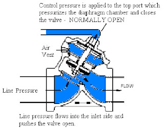
    In the Aquamatic world, a Normally Open Valve means when water or air passes through the inlet side of an Aquamatic Valve, the Aquamatic Valve will open to allow the water or air to flow through it. More simply put, in a Normally Open configuration, line pressure opens the valve, and control pressure closes the valve.

    So, the only way to close this valve is to apply control pressure into the Aquamatic Valve’s diaphragm chamber through the control port on top of the valve cap. This control pressure can be either water or air, and the pressure has to be equal or greater than the line pressure. Equal pressure will close the valve because the surface area of the diaphragm chamber is greater than the surface area of the inlet hole of the valve.

    Here is a diagram showing the function of a Normally Open Valve:


    Normally OPEN AquaMatic diaphragm valve cross-section showing how the control pressure actuates the valve.

    In looking at the diagram, water flowing into the valve, will open up the valve in a Normally Open valve configuration, and the control pressure applied to the diaphragm, chamber will close the valve. From a visual standpoint, if one sees a small tubing line connected to the top of the Aquamatic Valve’s cap, that is a good indication the valve is Normally Open.

    So how does a Normally Closed Aquamatic Valve work?
    A Normally Closed Valve means when water or air passes through the inlet side of an Aquamatic Valve, the Aquamatic Valve will close stopping the flow of water or air. Said another way, in a Normally Closed configuration, line pressure closes the valve, and control pressure opens the valve.

    There is a shaft inside the Aquamatic Valves that holds the other parts in place. A Normally Closed Valve has a hollow shaft. The hollow shaft allows the line pressure, water or air, to flow up the shaft into the diaphragm chamber. This pressurizes the diaphragm chamber, which then push the parts down closing the Aquamatic Valve. A pipe plug is inserted in the port on top of the valve cap to keep the water or air pressure from escaping the valve. In order to open up this valve, control pressure is applied to a port that is typically located underneath the valve cap, which forces the valve in the open stage. Here is a diagram showing how a Normally Closed Valve functions:

    Normally CLOSED AquaMatic diaphragm valve cross-section showing how the control pressure actuates the valve.

    The best way to determine if the valve is normally closed is to see if a pipe plug inserted on the valve cap.

    How can Res-Kem help me?
    Hopefully, I have been able to explain the difference between Normally Open or Normally Closed AquaMatic valves. If not, we usually recommend you email pictures to me. Res-Kem also offers question forms with visuals to also assist.

    AquaMatic K52 Series Question Guide
    AquaMatic K530 Series Question Guide
    AquaMatic V42 Series Question Guide
    AquaMatic VAV Series Question Guide

    Also look at our videos of how to select and repair AquaMatic valves.

    If you have any questions, please email me, Mike Polito, or contact me for further assistance at 800-323-1983.